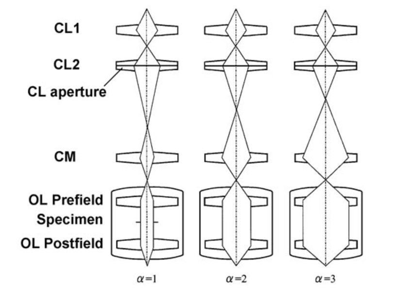
The parameter alpha describes the angle of the electron beam as it enters the objective lens (OL in the diagrams below). The diagrams below show the central portion of the optics of the JEOL JEM 3200FS and are built around the condenser lenses 1 and 2 (labeled CL1 and CL2, respectively), the condenser aperture associated with the second condenser lens (labeled simply CL aperture), the condenser mini lens (labeled CM), the specimen location (labeled Specimen and only shown in the leftmost diagram) and the pre- and postfields of the objective lens (labeled OL Prefield and OL Postfield, respectively).
The three panels below show ray tracing type diagrams for alpha settings 1 through 3 (left to right) under conditions where the beam is parallel (neither convergent nor divergent) as it passes through both halves of the objective lens. One thing that is immediately apparent is that as the alpha setting changes from 1 to 3, the width of the parallel beam increases. This is shown with real images at the bottom of this page. It should also be clear that as alpha changes from 1 to 3, the angle of the beam as it enters the objective lens (measured from the optical axis, the line running vertically in each panel) increases.

In each of these images, the alpha was set to 1, 2 or 3, the beam was made as parallel as possible, and a short exposure (showing the width of the beam) was recorded using the UtlraScan 4000.
Images coming soon!

