

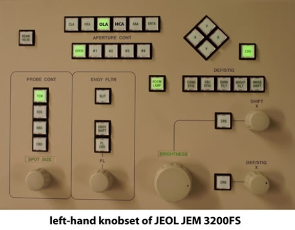
The objective lens apertures (OLA) and high contrast apertures (HCA) both occur after the specimen and along the optical path of the JEOL JEM 3200FS. The OLA sits very close to (but not exactly at) the back focal plane of the objective lens while the HCA is further away from that first diffraction plane. The OLA is sometimes called an in-gap aperture to distinguish it from the HCA which sits further from the specimen. Since neither aperture sits exactly in a diffraction plane, they are both visible in images at magnifications that are "low enough" (view our series of images that illustrates this visibility). Both the OLA and the HCA apertures are used to enhance the contrast of transmission electron microscope (TEM) images collected using the 3200FS
Effect of OLA and HCA Apertures on JEOL JEM 3200FS Images
How Apertures Create Contrast
Remember that TEM images are phase contrast images, and that when a perfect phase contrast specimen is recorded at focus using ideal lenses, everything in the image vanishes. No TEM specimen acts as a perfect phase contrast object, but the thinner the specimen is, the more like a perfect phase contrast object it behaves (and consequently, the less visible it becomes as TEM images get closer and closer to focus). This is especially true for images of ice-embedded biological materials, where the low atomic number of the major elements (C, N, and O) results in low overall electron scattering. This low intrinsic contrast can be improved both through the use of an energy filter (which eliminates imaging artifacts due to chromatic aberration) and by recording images far from focus (where the defocus introduces contrast). These effects are illustrated in a series of images recorded on our 3200FS.
In addition to defocus and the use of an energy filter, on the 3200FS, both the OLA and the HCA can be used to enhance contrast in images of ice-embedded biological (and any other type of) samples. The contrast enhancement due to these apertures can be explained by considering perfect phase contrast objects and ideal imaging systems more closely. The keys to having everything vanish in an in-focus image of a perfect phase contrast object are that
- all the electrons (or photons, for phase contrast light microscopy) scattered by the specimen must be collected by the imaging system
- when the image is at focus using a perfect lens, all the electron/photon waves arrive at the image plane in phase (meaning that if their pathlengths are measured, they are all integer multiples of the wavelength, λ).
Contrast arises when not all the electrons or photons are collected by the imaging system (the "lost" illumination causes fluxuations in the image's contrast) and/or when the image is not at focus (in which case the electron/photon waves are out of phase and interfere with each other both constructively and destructively). In addition to real TEM samples being non-perfect phase contrast objects, keep in mind that TEM lenses are also far from perfect. This means that TEM images will always have some amount of contrast, even though various factors that the user both can and cannot control will affect the actual contrast in any given image.
When using a TEM, images of real specimens will always suffer from the fact that not all the electrons are collected by the imaging system. For example, a small percentage of scattered electrons will be back-scattered (returned in the direction of the electron source) or scattered at forward angles so large that they are not collected by the post-specimen lenses.
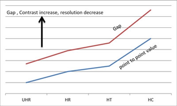
The inability to collect all (most) of the scattered electrons is a key difference between what an electron microscope manufacturer might call a "high resolution pole piece" and a "not high resolution pole piece." One major difference in such pole pieces (the magnetic lenses that form the objective lens) is the size of the gap along the optical axis, where (for example) a high resolution pole piece will have a smaller gap than a high contrast pole piece. For example, the graph to the right (obtained from JEOL USA) lists the pole pieces that are available for our JEOL 3200FS along the bottom and shows the relative trends for the four different pole pieces along the vertical axis of both the pole piece gap (red line) and the point resolution (blue line).
NOTE: The actual size of the pole piece gaps is proprietary information but numerical values for point resolutions are listed as 0.17 nm (ultra high resolution pole piece - UTR), 0.19 nm (high resolution pole piece - HR), 0.21 nm (high tilt pole piece - HT) and 0.26 nm (high contrast pole piece - HC). As noted in this figure, the point resolution decreases and the contrast increases as the pole piece gap increases.
Returning to the previous discussion, a smaller pole piece gap means that electrons scattered at larger angles can still be collected by the post-specimen lenses. This produces higher resolution images but at the expense of contrast: since many more of the scattered electrons are collected by the lenses, the contrast (especially in at-focus images) is intrinsically lower.
Also bear in mind that as the forward scattering angle increases, the probability of an electron scattering at that angle decreases. This means that there are fewer and fewer of these highly scattered electrons as the scattering angle grows larger and larger. Since the smaller the pole piece gap is, the harder it is to deal with the mechanics of the specimen holder and any additional hardware that needs to be inside the pole piece, this angular dependence on the number of scattered electrons implies that there will be trade-offs between the angles of scattered electrons that can be collected and the size of pole piece gap.
Visible Effects of the OLA and HCA
Post-specimen apertures like the OLA and HCA simply enhance the effect caused by collecting more or fewer scattered electrons: as such annular apertures get smaller and smaller, they eliminate more and more of the electrons in the forward scattered beam. This makes the imaging hardware less like a perfect phase contrast system (i.e., fewer and fewer of the total number of electrons are recovered), and that leads to greater image contrast. These same highly scattered electrons that are stopped by these annular apertures also contain higher and higher resolution information, and as these electrons are eliminated, the resolution in the image descrease. An easy way to see this directly is to look at electron diffraction patterns from a standard "waffle grid" with and without the apertures. These grids have a replica diffraction grating pattern made from sputtered Au/Pd, and the waffle pattern visible at low magnification actually consistents of poly-crystalline islands of these metals. The electron diffraction pattern is essentially a powder diffraction pattern from the many nanocyrstalline islands of metal. The fundamental spacing between the layers of atoms in these crystals (the d-spacing, which also corresponds to the resolution of the inner-most ring in this diffraction pattern) in these images is 2.35 Å. There is a faint ring seen in the upper left portion of the images below (the areas marked "over-exposed, no aperture") at about 3.5x the radius of the inner-most ring.
Our 3200FS uses JEOL's high resolution pole piece with it's relatively narrow pole piece gap. It was initially purchased without a OLA since the narrow gap and the standard OLA aperture unit interfered with the sample tilting we wanted to do with this instrument. By the time our 3200FS had been in operation about a year, JEOL had designed a new OLA unit that had only a modest effect on its tilting capability. Installation of the new unit (which only contains 3 apertures) solved several performance issues we experienced with biological samples.
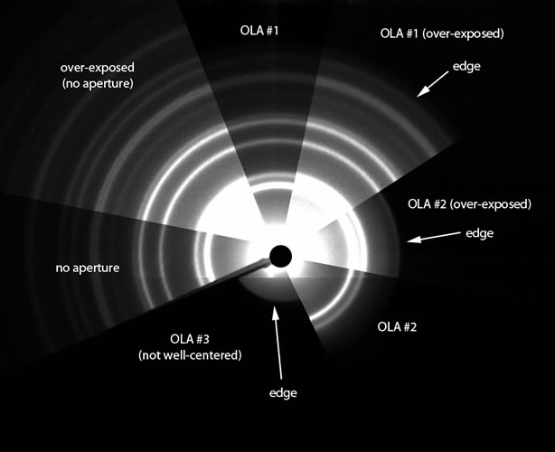
As of July 1, 2013, the 3 OLA apertures in our JEOL 3200FS have diameters of 120, 60 and 40 μm (in positions 1 thru 3). The image to the right shows the effect of these 3 apertures on the electron diffraction pattern from a standard "waffle grid".
As is clearly seen in the image above, the largest aperture (#1) passes very high resolution information to the rest of the imaging system but does block some of the scattered electrons that are clearly visible in this diffraction pattern. At the other extreme, the smallest aperture (3#) blocks all the electrons scattered at the Bragg angles of the polycrystalline Au/Pd.
The following section needs work!
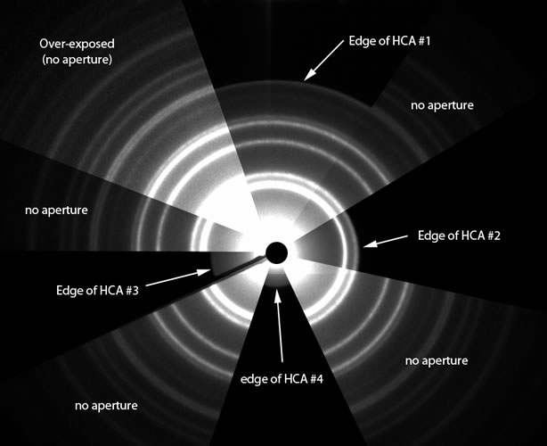
As of July 1, 2013, the HCA holds 4 apertures (120, 60, 40 and 20 μm diameter in positions 1 thru 4). Since it sits even further away from a diffraction plane in the post-specimen lenses, an HCA aperture indentical in size to one in the OLA will eliminate more electrons scattered at smaller angles than what is seen with the OLA. For example, compare OLA #3 to HCA #3