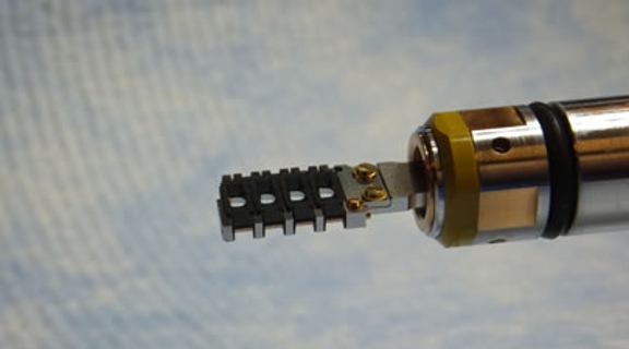
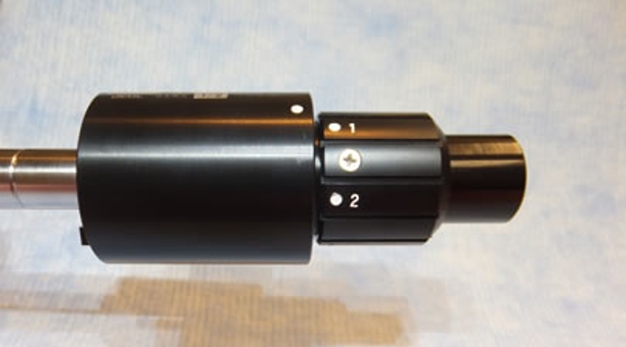
The specimen quartet holder can hold up to four grids that are independently clamped into position by the black, hinged pieces shown in this image. As described below, different grids are examined by extending and retracting the tip of the holder. This image shows the holder set to examine grid #1 (the grid closest to the tip of the holder).
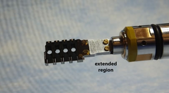
Once inside the microscope, the user selects which grid to examine by twisting the end of the holder away from the grids (see below). There are four set positions within this mechanism that extend and retract the grid holding region so that the different grids are in the path of the electron beam. This image shows the holder set to examine grid #4 (the grid furthest from the tip of the holder).
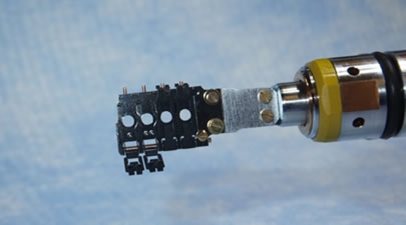
To load grids into this holder, one or more of the individual black clamps are released from their locked position (the hinge is closer to the viewer in this image), a grid is placed in the circular well that is exposed when the clamp is opened and the clamp is closed again. This image shows two clamps open (for grids #1 & #2) while the other two clamps (for grids #3 & #4) are closed.
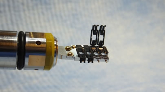
This image shows the holder in the same state as the previous image, but was recorded from the opposite side. In this image, the hinges of the clamps are further from the viewer and it is easier to see the pins that guide the clamps into position.
The opposite end of the holder houses the mechanism that controls which grid is examined. The user lines up the grid number (1 thru 4) with the large white dot to select a particular grid. In this image, the holder is set to examine grid #1 (the first grid from the tip of the holder).
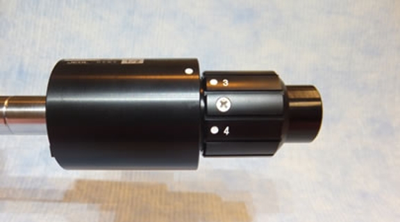
Now the holder is set to examine grid #3 (the third grid from the tip of the holder). Note that the very end of the holder has changed position between these two images.